Tools & Materials
Leaf blower barely blowing? It's time to face the fix. Whether you are a seasoned landscaper or a yearly yard-shaper, eReplacementParts.com provides the parts, procedures and facts you need to fearlessly fix what fails you.
As with all of your outdoor power equipment, your handheld leaf blower will require some periodic maintenance to keep it running strong. Basic yearly maintenance on your leaf blower should include replacing the spark plug, the air filter and the fuel filter.
At some point, you'll probably need to rebuild your carburetor as well; especially as the amount of ethanol in our gasoline continues to increase.
This article provides step-by-step instructions for rebuilding the carburetor, as well as removing and installing the spark plug, air filter and fuel filter on a 2-cycle handheld leaf blower.
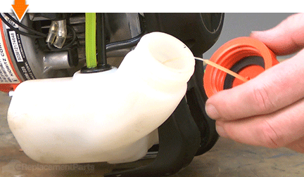
Let's get started. PART 1: REPLACING THE FUEL FILTER [top] 1. Remove the fuel cap.
Unscrew and remove the fuel cap from the fuel tank.
2. Remove the fuel filter from the fuel line.
To make your own fuel line retriever; curve the end of a sturdy length of wire into the shape of a hook.
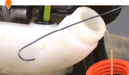
Insert the wire hook into the fuel tank and retrieve the line containing the fuel filter.
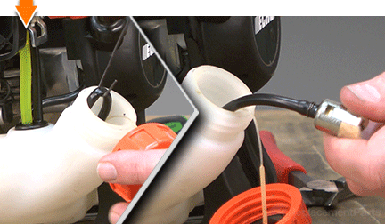
Remove the fuel filter from the fuel line with a twisting and pulling motion.
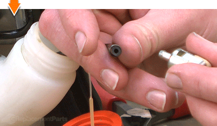
Remove the fuel line clip.
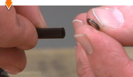
3. Install the new fuel filter.
Slide the fuel line clip over the fuel tube and hold the clip approximately 1/4 of an inch from the end of the tube.
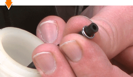
Install the new fuel filter onto the end of the fuel tube. The clip should expand slightly to accommodate the flared connection, and then tighten around the narrow portion of the fitting. Perform this step in one continuous motion. If the clip slides backwards (further onto the onto the fuel tube), reposition the clip and start again.
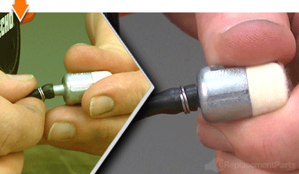
4. Reinstall the fuel filter into the fuel tank.
Insert the fuel filter (and fuel line) into the fuel tank.
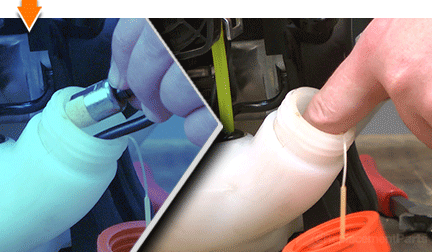
5. Reinstall the fuel cap.
Reinstall the fuel cap onto the fuel tank.
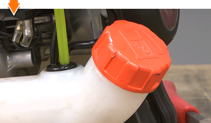
PART 2: REPLACING THE AIR FILTER [top] 1. Remove the air filter cover.
Loosen the thumb screw.
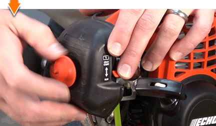
Remove the air filter cover.
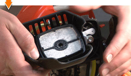
2. Remove the air filter.
Remove the air filter.
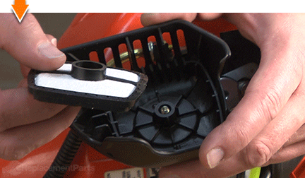
3. Install the new air filter.
Install the new air filter into the cover (or onto the air cleaner case).
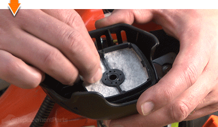
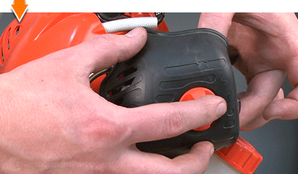
4. Reinstall the air filter cover.
Install and secure the air filter cover.
PART 3: REPLACING THE SPARK PLUG [top] 1. Remove the spark plug.
Remove the spark plug boot from the spark plug.
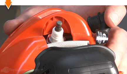
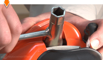
Use a spark plug wrench (or socket) to loosen the spark plug.
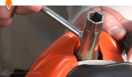
Remove the spark plug from the cylinder head.
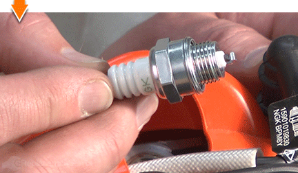
2. Set the gap on the new spark plug.
The gap is the distance between the ground electrode (metal strap) and the center electrode. This distance is measured (and adjusted) with a spark plug gapping tool. Adjustments are made by moving the strap closer to (or farther from) the center electrode.
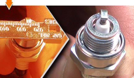
Measure and adjust the gap (as necessary) to seven-tenths of a millimeter (0.07 mm).
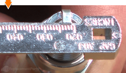
3. Install the new spark plug.
Thread the new spark plug into the cylinder head.
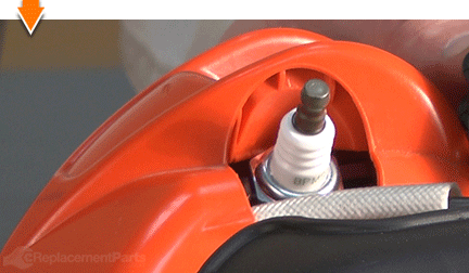
Secure the spark plug with a wrench.
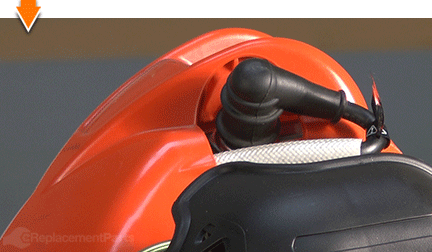
Replace the spark plug boot.
PART 4a: REMOVING THE CARBURETOR [top] 1. Remove the air cleaner assembly.
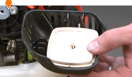
Loosen the thumb screw.

Remove the air filter and cover.
2. Drain the fuel.
Drain the fuel before servicing the unit.
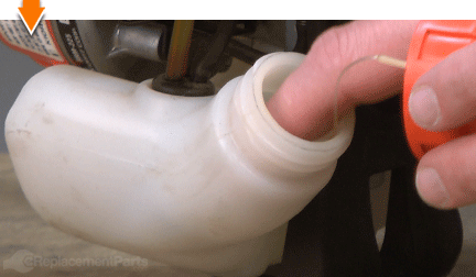
3. Remove the air filter case.
Loosen the (2) bracket retaining screws.
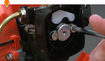
Remove the air filter case (along with the bracket and the screws) from the engine.
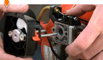
4. Remove the carburetor.
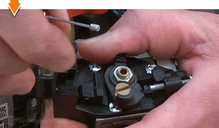
Use a wrench to loosen the throttle cable adjusting nut.
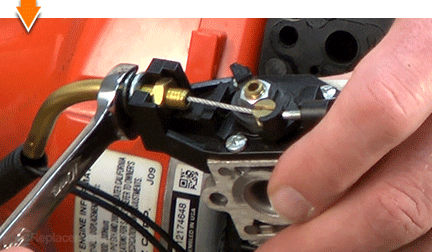
Disconnect the throttle cable from the throttle body.
Disconnect the (2) fuel lines from the carburetor.
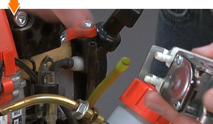
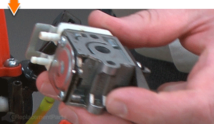
Remove the carburetor from the engine.
PART 4b: DISASSEMBLING THE CARBURETOR [top] 5. Remove the rotor cover assembly (throttle body).
Remove the (3) screws from the top of the rotor cover assembly.
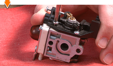
Remove the (1) screw from the side of the rotor cover assembly.
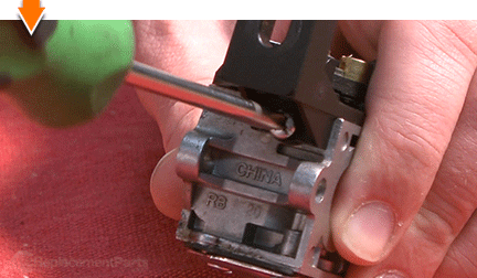
Lift the rotor cover assembly away from the carburetor.
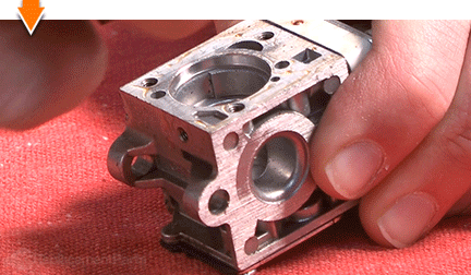
Use a pick or small screwdriver to remove the O-ring from the throttle body.
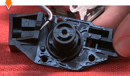
6. Remove the guide roller.
Use long-nosed pliers to remove the metal roller from the mounting post in the carburetor.
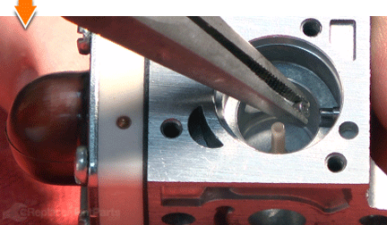
7. Remove the primer bulb.
Remove the (4) screws from the primer pump cover (plate).
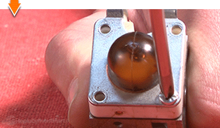
Remove the primer pump cover (plate) from the carburetor.
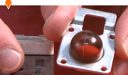
Remove the primer bulb from the carburetor.
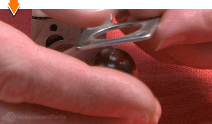
8. Remove the purge base assembly.
Remove the (1) screw from the purge base assembly.
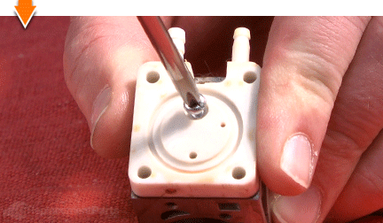
Remove the purge base assembly from the carburetor.
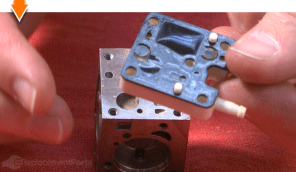
Remove the reed valve from the purge base assembly (or the carburetor).
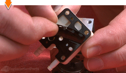
Remove the gasket from the purge base assembly (or the carburetor).
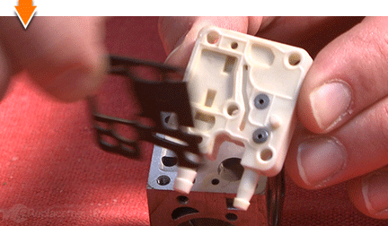
Use a pick or small screwdriver to remove the metal filter from the carburetor.
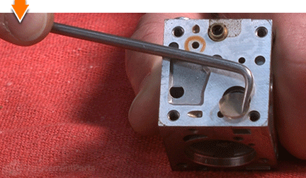
9. Remove the metering cover.
Remove the (2) screws from the metering cover.
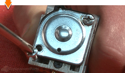
Remove the metering cover from the carburetor.
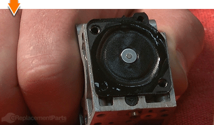
Remove the diaphragm from the carburetor.
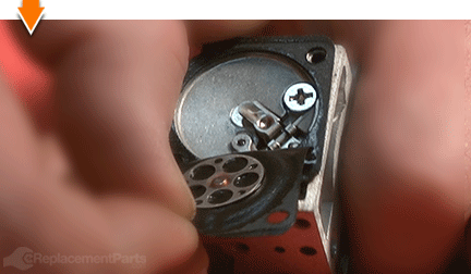
Remove the metering gasket from the carburetor.
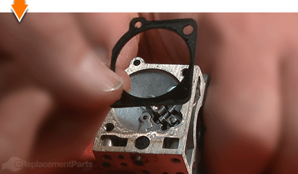
10. Remove the metering lever and needle.
The metering lever is spring-loaded; place your finger over the lever to prevent the assembly from springing out of the carburetor as you remove the screw.
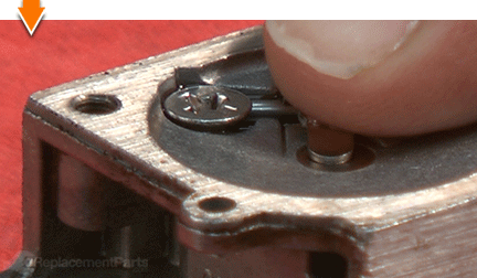
Remove the metering lever pin screw.
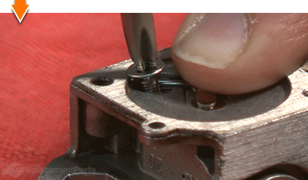
Slowly release tension from the metering lever.
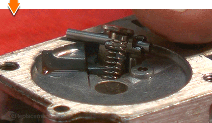
Remove the metering lever and hinge pin from the carburetor.
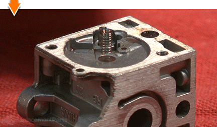
Remove the lever spring from the carburetor.
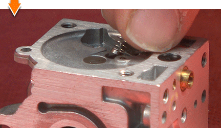
Remove the needle from the carburetor.
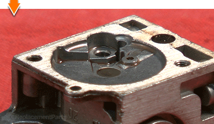
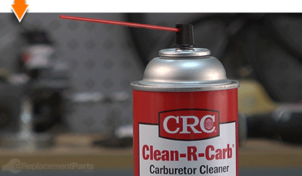
PART 4c: CLEANING THE CARBURETOR [top] There are two general methods for cleaning the carburetor. The traditional (chemical) method uses carburetor cleaner spray to dissolve grime, varnish and carbon residue.
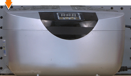
The alternative method requires an ultrasonic cleaner, which uses ultrasonic shockwaves (and water) to clean carburetor components. Both methods are described below.
11(A). Cleaning with chemical spray.
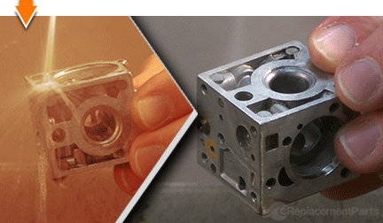
Liberally spray/clean the metal body of the carburetor (according to the directions on your specific brand of carburetor cleaner).
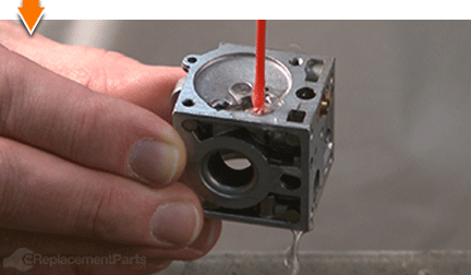
Use the long plastic nozzle to direct the spray into of each of the tiny openings on the carburetor body. However, do not actually insert the nozzle (or any metal objects) into the openings. Doing so may damage the carburetor. Fishing line may be used to safely clear/clean badly obstructed passages.
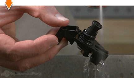
Liberally spray/clean the throttle body assembly.
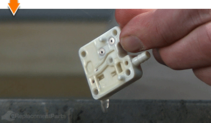
Liberally spray/clean the purge base assembly.
11(B). Cleaning with an ultrasonic cleaner.
Insert the carburetor, purge base assembly, and throttle body assembly into the cleaning tank.
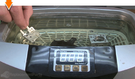
Activate the ultrasonic cleaner (according to the directions on your specific model).
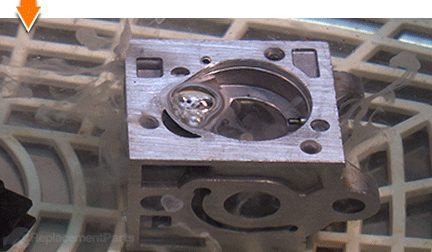
Remove the components from the cleaning tank.
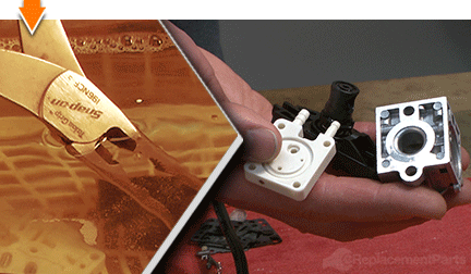
Rinse the components with clean water.
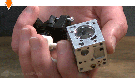
12. Remove excess water from the cleaned components.
Regardless of the cleaning method employed, use compressed air (with blower nozzle) to remove excess water (or cleaner) from the carburetor, purge base assembly, and throttle body assembly.
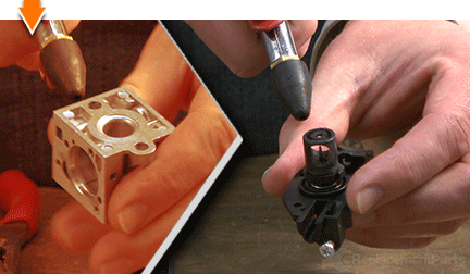
PART 4d: REBUILDING THE CARBURETOR [top] 13. Install the metering lever and needle.
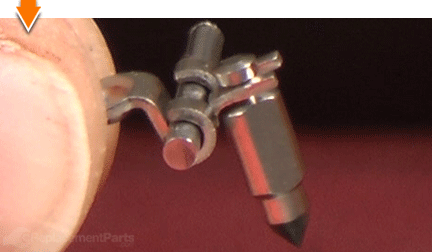
Install the head of the metering needle into the fork of the metering lever.
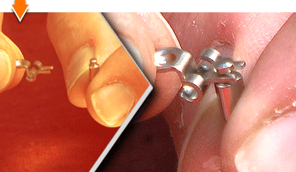
Install the lever hinge pin onto the metering lever. (The hinge pin should pass through both of the hinges on the metering lever.)
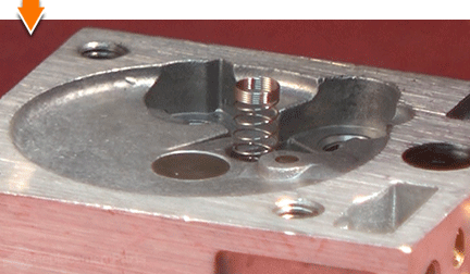
Insert the valve spring into the mounting hole on the carburetor body.
Install the metering needle and lever assembly into the carburetor body. The needle should slide into the hole. The hinge pin should seat snugly within the body of the carburetor (i.e. the pin will align itself laterally in order to fit correctly into the body).
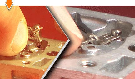
Align the metering lever above the spring.
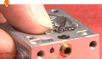
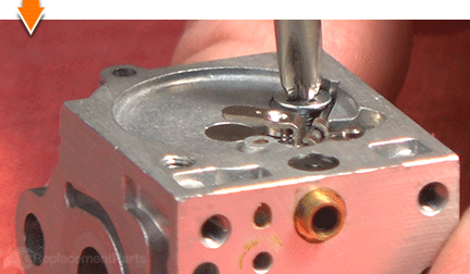
Secure the metering lever and needle assembly with the screw.
14. Install the diaphragm and gasket. (Needle-side of carburetor.)
Place the gasket on the carburetor body and align the mounting holes.
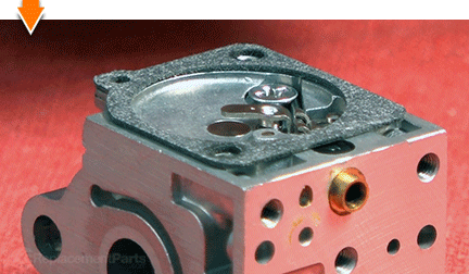
Place the diaphragm over the gasket and align the mounting holes. The metal portion of the diaphragm should face down.
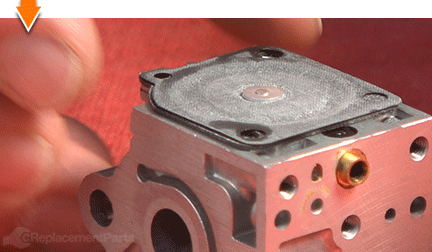
Place the metering cover over the diaphragm and gasket.
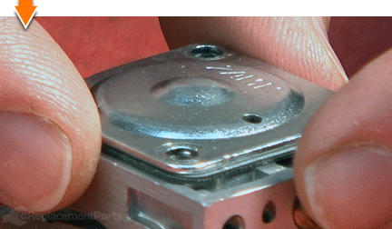
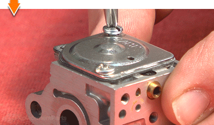
Secure the metering cover with the (2) screws.
15. Install the reed valve and gasket. (Primer-side of carburetor).
Install the filter into the recess on the carburetor body.
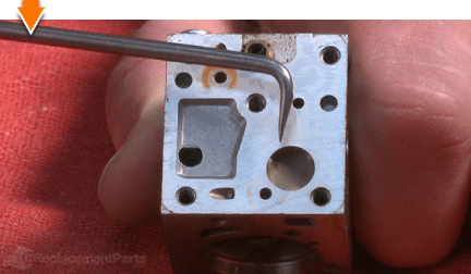
Place the reed valve on the carburetor body and align the mounting holes.
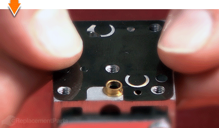
Place the gasket over the reed valve and align the mounting holes.
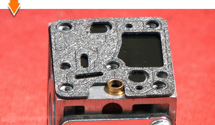
Install the purge base assembly over the gasket.
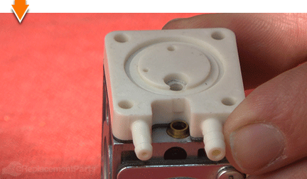
Secure the purge base assembly to the carburetor with the (1) screw.
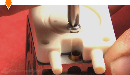
16. Install the primer bulb and cover.
Install the primer bulb onto the purge base assembly.
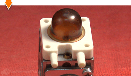
Install the primer pump cover (metal plate) onto the purge base assembly.
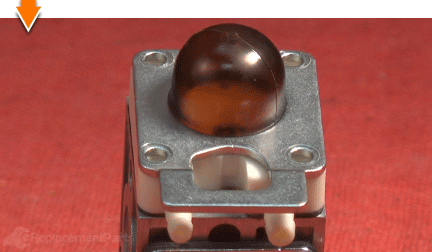
Secure the primer pump cover with the (4) screws. (Tighten these screws evenly.)
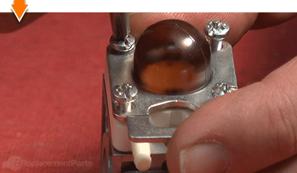
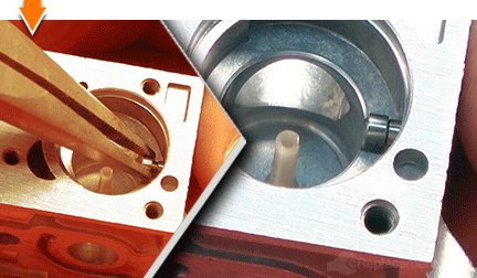
17. Install the guide roller. (Throttle-side of carburetor.)
Use long-nosed pliers to slide the roller onto the mounting post in the carburetor.
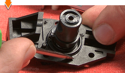
18. Install the O-Ring on the rotor cover (throttle body).
Install the O-ring onto the throttle rotor.
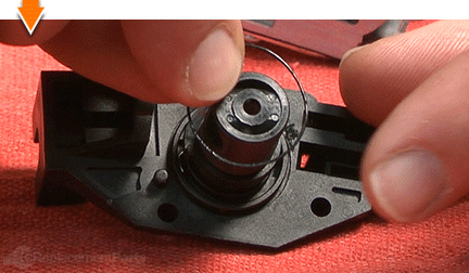
Use a small screwdriver to seat the O-ring around the rim of the throttle rotor.
19. Reinstall the rotor cover assembly (throttle body).
Install the rotor cover assembly onto the carburetor.
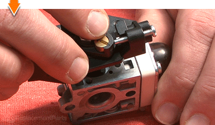
Secure the (3) screws on the top of the rotor cover assembly.
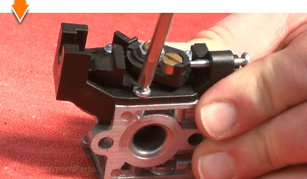
Secure the (1) screw on the side of the rotor cover assembly.
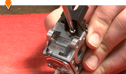
20. Connect the fuel lines to the carburetor.
Remove the gas cap and locate the fuel filter. The filter will be attached to the INCOMING fuel line. Make note of this fuel line for use in the next step.
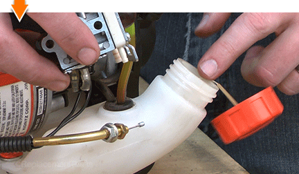
Plug either one of the carburetor ports with the tip of your finger; depress the primer bulb several times. If the primer bulb softens (deflates) without returning to its original shape; you have plugged (and identified) the incoming port.
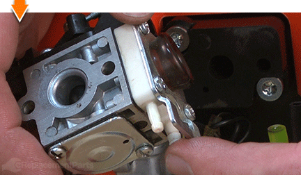
If the primer bulb fills with air (hardens) and wont allow further priming; you have plugged (and identified) the RETURN port.
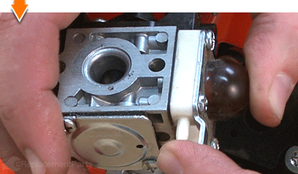
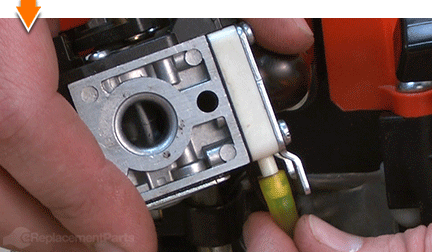
Connect the INCOMING fuel line to the INTAKE port on the carburetor.
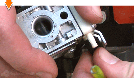
Connect the RETURN fuel line to the RETURN port on the carburetor.
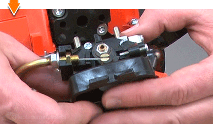
21. Reinstall the throttle cable to the carburetor.
Rotate the throttle lever on the carburetor to fully open the throttle.
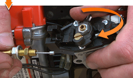
Thread the throttle cable through the brass connector on the top of the carburetor.
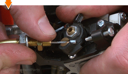
Pull back slightly on the throttle cable (away from the carburetor) to secure the tip of the cable beneath the slots of brass connector.
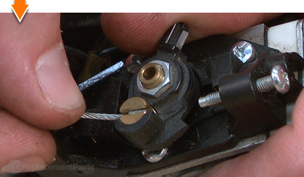
Press the throttle adjustment nut (on the cable) into the recess on the throttle body.
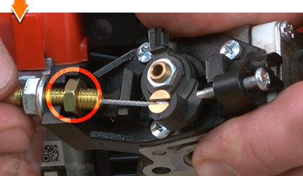
Use a wrench to secure the secondary throttle nut.
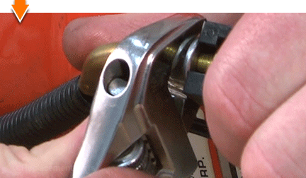
22. Reinstall the carburetor.
Thread the (2) mounting screws through the mounting holes on the air cleaner bracket and the air cleaner case. The bracket should be flush against the interior of the air cleaner case (on the same side as the choke valve).
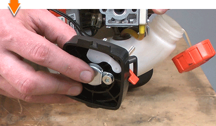
Thread the screws (protruding from the air cleaner case) through the holes on the carburetor assembly.
Note that there are two small holes on the intake gasket (besides the main intake opening and the two mounting holes). These small holes need to align with the small hole on the insulator block.
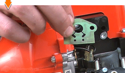
Thread the screws through the mounting holes on the intake gasket and slide the gasket flush against the carburetor.
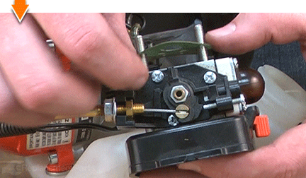
Install the intake assembly (bracket, air cleaner case, carburetor and intake gasket) onto the intake insulator block.
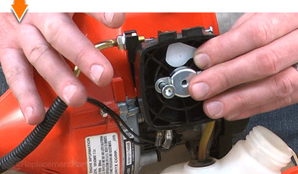
Secure the intake components (bracket, air cleaner case, carburetor and intake gasket) with the screws.
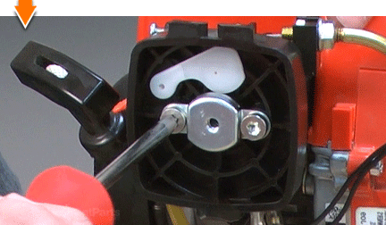
23. Reinstall the air filter and cover.
Install the air filter into the cover.

Install the air filter cover and secure the thumbscrew.

You don't have to leverage your savings to level your lawns. As you just learned, repairing your outdoor equipment is easy when you follow our step-by-step guides. Not only did you restore blower functionality at a fraction of the cost of replacement; you have the cleared the way for future repairs wherever you may find them.


